Mechanical
Devices
Below is a collection of revision 'flashcards' that cover the exact key terms found in the UK GCSE curriculum Design and Technology syllabus. Take your time to learn and remember the terms on each flash card. Real world examples are also provided for use in written exam answers!

Types of Motion
Glossary of Key Terms
-
Linear Motion
-
Reciprocating Motion
-
Oscillating Motion
-
Rotary Motion

Linear motion describes movement in a straight line along a single axis. In machines, this type of motion is crucial for various tasks. Imagine a printer head moving back and forth to lay down ink, or a robotic arm extending to pick up an object. Linear motion devices, like pistons in an engine or lead screws in a 3D printer, convert rotary motion (circular) from motors into precise linear movement. Understanding linear motion is key to designing mechanisms that push, pull, or position objects accurately in a machine.

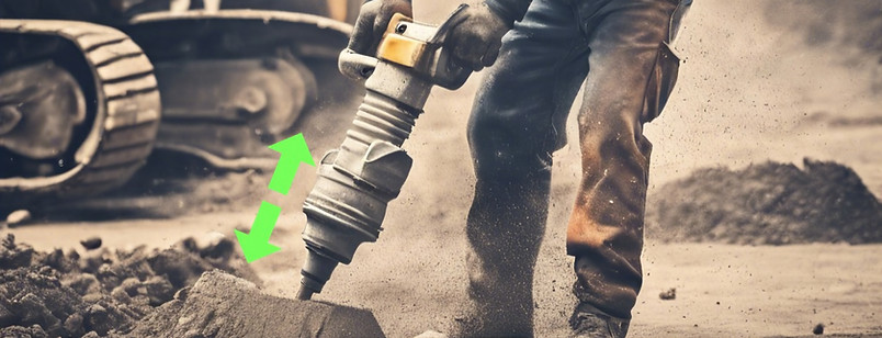
Reciprocating motion refers to a specific type of linear motion where an object moves back and forth repeatedly in a straight line. Imagine a saw moving up and down to cut wood, or a sewing machine needle pushing the thread through fabric. Unlike simple linear motion, reciprocating motion involves constant reversal of direction. Many machines rely on mechanisms like crankshafts and connecting rods to convert rotary motion into this back-and-forth action. Reciprocating motion is essential in engines, pumps, saws, and many other devices where controlled pushing and pulling are needed.

Oscillating motion describes a repetitive movement of an object back and forth around a fixed point. Think of a playground swing moving forward and backward, or a pendulum clock swinging from side to side. Unlike reciprocating motion which is strictly linear, oscillating motion can involve a swinging or rocking movement. Springs, pendulums, and balance wheels in watches are all examples of mechanisms that use oscillation. This type of motion is used for timekeeping, controlling valves, and even creating vibrations for tasks like mixing or cleaning.

Rotary motion refers to the continuous circular movement of an object around a fixed axis. This is a fundamental type of motion in machines, and you'll see it everywhere from wheels turning on a car to gears spinning in a clock. Imagine a drill bit rotating to create a hole, or a fan blade spinning to generate airflow. Rotary motion is often used as a starting point, with motors or engines creating the rotation that can be transferred to other parts of a machine. Devices like gears, belts, and pulleys can then be used to change the speed, direction, or amount of force (torque) of this rotary motion. By controlling and manipulating rotary motion, we can achieve a vast range of functions in machines.

Levers
Glossary of Key Terms
-
First Order levers
-
Second Order levers
-
Third Order levers

A first-order lever is a simple machine with a bar that pivots on a fixed point (fulcrum). By applying force (effort) at one end, you can lift a load (weight) on the other. See-saws and crowbars are common examples. These levers can change the direction or amount of force needed to complete a task.

Second-order levers put the load (the weight you want to move) between the fulcrum (pivot point) and the effort (the force you apply). Think of a wheelbarrow - the handles are the effort point, the wheel axle is the fulcrum, and the heavy load you're carrying rests between them. This arrangement always gives you a mechanical advantage, meaning you can use less force to move a heavier object. Bottle openers and nutcrackers also work on this principle, making them easier to use than lifting the object directly.

Third-order levers might require a little more effort from you, but they offer a trade-off. In these levers, the effort (force you apply) is placed between the fulcrum (pivot point) and the load (weight you want to move). Imagine a pair of tweezers - you squeeze the handles (effort) closer together to grip a small object (load) at the tip. While you may need to use more force than the weight of the object itself, third-order levers give you a greater range of movement or more precise control over the load, making them ideal for tasks requiring dexterity. Fishing rods and shovels are other examples of this type of lever.

Linkages
Glossary of Key Terms
-
Bell Crank linkages
-
Push/pull linkages
A bell-crank linkage is a simple but versatile mechanism that changes the direction of force or motion in a machine. Imagine a bent lever shaped like a bell - that's where it gets its name! The bend acts as a pivot point, and by applying force to one arm, the linkage transmits that force in a perpendicular direction out the other arm. This makes them perfect for situations where you need to turn a corner or redirect movement, like in bicycle brakes or aircraft control systems. Bell-crank linkages are like little workhorses, helping us transfer and control forces in various machines.


Push-pull linkages keeps things simple. Unlike some linkages that change direction, a push-pull linkage does exactly what it sounds like: it transmits a push or pull force in the same direction. Imagine a set of parallel bars connected by pivots. By pushing or pulling on one bar, the other bar moves in the same direction, maintaining a constant distance between them. This makes them ideal for applications where you need a linear push or pull force to be transmitted over a distance without any change in direction. Overhead doors and suspension systems in some cars use push-pull linkages to achieve this kind of movement.

Rotary Systems
Glossary of Key Terms
-
CAMs and Followers
-
Gear Trains
-
Rack & Pinion systems
-
Pulleys & Belt systems
-
Velocity Ratio (Maths)

In machines, a cam and follower duo work together to convert rotary motion into another type of movement. Imagine a bumpy wheel (the cam) spinning against a smooth rod (the follower). The bumps on the cam push the follower in different directions as it rotates. This allows the cam to control the follower's linear back-and-forth (reciprocating) or swinging (oscillating) movement. Cams are essential parts in many machines, from car engines to sewing machines, precisely controlling how components move.

Gear trains are the workhorses of many machines, acting like sets of intermeshing wheels that transmit rotational motion and power. Imagine a series of gears with different sized teeth fitting together. By changing the size ratio of the gears, a gear train can increase or decrease the speed of rotation, change its direction, or even multiply the torque (turning force). This makes them incredibly versatile for controlling and manipulating motion in everything from bicycles to clocks and even giant wind turbines.

A rack and pinion system is a simple but effective mechanism for converting rotary motion into linear motion. Imagine a gear (the pinion) that looks like a small round wheel with teeth. This pinion meshes with a straight bar that has teeth along its entire length (the rack). When you turn the pinion gear, it acts like a crank, pushing the rack back and forth in a straight line. This back-and-forth movement is very precise and efficient, making rack and pinion systems ideal for steering cars, moving elevator cabins, and even operating 3D printers.

Belt and pulley systems work together to transmit rotary motion and power over distances. Imagine a looped belt wrapped around grooved wheels (pulleys). As one pulley spins, the belt transfers that rotation to the other pulley. By using different sized pulleys, you can change the speed of the rotation or even reverse its direction. Belt and pulley systems are quieter and more flexible than gear trains, making them ideal for situations where you need smooth power transfer over a distance, You'll find them in everything from lawnmowers and vacuum cleaners to car engines and clothes dryers.

The velocity ratio in both pulley and gear systems tells you how much the speed of rotation changes between the input and output. It's essentially a ratio between the driving force and the driven force. In both systems, the calculation is based on the size of the respective parts.
-
For gear trains: The velocity ratio is calculated by dividing the number of teeth on the driven gear by the number of teeth on the driving gear. So, a bigger driven gear compared to the driver gear means a slower output speed (higher ratio).
-
For pulley systems: The ratio is calculated by dividing the diameter of the driven pulley by the diameter of the driving pulley. Similar to gears, a larger driven pulley relative to the driver gives you a slower output speed.
Remember, regardless of the system, a velocity ratio greater than 1 indicates a slower output speed compared to the input. A ratio of 1 means the speeds are the same, and a ratio less than 1 means the output speed is faster than the input. Calculations like these are used to find out the Mechanical Advantage of a system. The greater the Mechanical Advantage, the more power, more energy efficient or more safe the system becomes for its purpose.
Real World Example:
Rolex
In the age of smartphones and wearable tech, it might be hard to understand why customers still prefer to buy watches with mechanical movements and clockwork springs. After all, an Apple smartwatch provides a lot more features and technology from fitness tracking to notifications.
Rolex, founded in 1905 in London, is the most famous luxury watch company today. Their analog watches are beautifully handcrafted with tiny mechanisms and movements. Customers still appreciate the fine detail and craftsmanship of Rolex watches, with the most expensive watch being sold for US 17.7 million dollars! There is beauty in even the smallest precision movements and customers are willing to pay for it!

Take a look at the complex gears, linkages, types of movements and rotary motions all packed into an area no larger than the width of your wrist!